Essentials connection-based routing
TL;DR
Routing is defined by a connection graph or a wiring diagram. Routable devices are sources, midpoints, or destinations. Devices are connected by tie lines. Tie lines represent the cables connecting devices, and have specific signal types (audio, video, audioVideo, usb). Routes are made by telling a destination to get a route from a source for a specific signal type. Combined signal types (e.g., audioVideo) are automatically split into separate routing operations.
Summary
Essentials routing is described by defining a graph of connections between devices in a system, typically in configuration. The audio, video and combination connections are like a wiring diagram. This graph is a collection of devices and tie lines, each tie line connecting a source device, source output port, destination device and destination input port. Tie lines are logically represented as a collection.
When routes are to be executed, Essentials will use this connection graph to decide on routes from source to destination. A method call is made on a destination, which says "destination, find a way for source xyz to get to you." An algorithm analyzes the tie lines, instantly walking backwards from the destination, down every connection until it finds a complete path from the source. If a connected path is found, the algorithm then walks forward through all midpoints to the destination, executing switches as required until the full route is complete. The developer or configurer only needs to say "destination, get source xyz" and Essentials figures out how, regardless of what devices lie in between.
Signal Type Handling
When a combined signal type like audioVideo is requested, Essentials automatically splits it into two separate routing operations—one for audio and one for video. Each signal type is routed independently through the system, ensuring that:
- Audio-only tie lines can be used for the audio portion
- Video-only tie lines can be used for the video portion
- AudioVideo tie lines can be used for both portions
During path discovery, only tie lines that support the requested signal type are considered. For example, if a video route is requested, only tie lines with the video flag will be evaluated. This ensures signal compatibility throughout the entire routing chain.
Port-Specific Routing
The routing system supports routing to and from specific ports on devices. You can specify:
- A specific input port on the destination device
- A specific output port on the source device
- Both specific ports for precise routing control
When no specific ports are specified, the algorithm will automatically discover the appropriate ports based on available tie lines.
Request Queuing
All routing requests are processed sequentially through a queue. For devices that implement warming/cooling behavior (e.g., projectors), route requests are automatically held when a device is cooling down and executed once the device is ready. This prevents routing errors and ensures proper device state management.
Classes Referenced
PepperDash.Essentials.Core.IRoutingSourcePepperDash.Essentials.Core.IRoutingOutputsPepperDash.Essentials.Core.IRoutingInputsPepperDash.Essentials.Core.IRoutingMidpointPepperDash.Essentials.Core.IRoutingMidpointWithFeedbackPepperDash.Essentials.Core.IRoutingSinkWithFeedback
Note: As of the v3 routing refactor, the older
IRoutingInputsOutputs,IRouting,IRoutingWithFeedback,IRoutingWithClear,IRoutingSink,IRoutingSinkWithInputPort,IRoutingSinkNoSwitching,IRoutingSinkWithSwitching, andIRoutingSinkWithSwitchingWithInputPortinterfaces have been removed and consolidated - see Routing interfaces (v3) below for the current mapping.
Example system, a simple presentation system
The diagram below shows the connections in a simple presentation system, with a few variations in connection paths. Example routes will be described following the diagram.
Each visible line between ports on devices represents a tie line. A tie line connects an output port on one device to an input port on another device, for example: an HDMI port on a document camera to an HDMI input on a matrix switcher. A tie line has a signal type (audio, video, audioVideo, or usb) that determines what signals can travel through it. It is essentially a logical representation of a physical cable in a system. This diagram has 12 tie lines, and those tie lines are defined in the tieLines array in configuration.
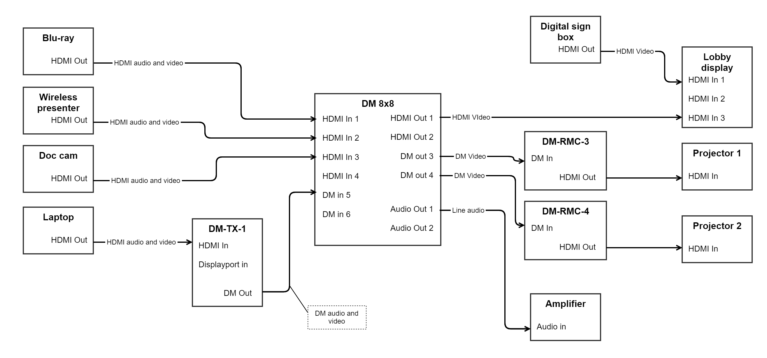
Let’s go through some examples of routing, using pseudo-code:
- Method call: “Projector 1, show Doc cam.” Routing will walk backwards through DM-RMC-3 and DM-8x8 iterating through all “wired up” ports until it finds a path back to the Doc cam. Routing will then step back through all devices in the discovered chain, switching routes on those that are switchable: Doc cam: no switching; DM 8x8: route input 3 to output 3; DM-RMC-3: no switching; Projector 1: Select input HDMI In. Route is complete.
- Method call: "Projector 2, show Laptop, video-only." Routing will walk backwards through DM-RMC-4, DM 8x8, DM-TX-1, iterating through all connected ports until it finds a connection to the laptop. During this search, only tie lines that support video signals are considered. Routing then steps back through all devices, switching video where it can: Laptop: No switching; DM-TX-1: Select HDMI in; DM 8x8: Route input 5 to output 4; DM-RMC-4: No switching; Projector 2: Select HDMI input. Route is complete.
- Method call: "Amplifier, connect Laptop audio." Again walking backwards to Laptop, as in #2 above, but this time only tie lines supporting audio signals are evaluated. Switching will take place on DM-TX-1, DM 8x8, audio-only.
- Very simple call: “Lobby display, show signage controller.” Routing will walk back on HDMI input 1 and immediately find the signage controller. It then does a switch to HDMI 1 on the display.
All four of the above could be logically combined in a series of calls to define a possible “scene” in a room: Put Document camera on Projector 1, put Laptop on Projector 2 and the audio, put Signage on the Lobby display. They key takeaway is that the developer doesn’t need to define what is involved in making a certain route. The person configuring the system defines how it’s wired up, and the code only needs to tell a given destination to get a source, likely through configuration as well.
All of the above routes can be defined in source list routing tables, covered elsewhere (make link).
Routing Algorithm Details
Combined Signal Type Splitting
When an audioVideo route is requested, the routing system automatically splits it into two independent routing operations:
- Audio Route: Finds the best path for audio signals from source to destination
- Video Route: Finds the best path for video signals from source to destination
Each route can take a different physical path through the system. For example:
- Video might travel: Laptop → DM-TX-1 → DM Matrix → Display
- Audio might travel: Laptop → DM-TX-1 → DM Matrix → Audio Processor → Amplifier
Both routes are discovered, stored, and executed independently. This allows for flexible system designs where audio and video follow different paths.
Signal Type Filtering
At each step of the route discovery process, the algorithm filters tie lines based on the requested signal type:
- Video request: Only considers tie lines with the
videoflag set - Audio request: Only considers tie lines with the
audioflag set - AudioVideo request: Routes audio and video separately, each following their respective filtering rules
If no tie line exists with the required signal type at any point in the chain, that path is rejected and the algorithm continues searching for an alternative route. If no valid path is found, the route request fails and no switching occurs.
This filtering ensures that incompatible signal types never interfere with routing decisions. For example, an audio-only cable will never be selected when routing video, preventing misconfiguration errors.
Definitions
Ports
Ports are logical representations of the input and output ports on a device.
Source
A source is a device at the beginning of a signal chain. For example, a set-top box, or a camera. Source devices typically have only output ports.
Source devices in Essentials must implement IRoutingOutputs or IRoutingSource
Midpoint
A midpoint is a device in the middle of the signal chain. Typically a switcher, matrix or otherwise. Examples: DM chassis; DM-TX; DM-RMC; A video codec. These devices will have input and output ports.
Passthrough midpoints (no active switching) must implement IRoutingMidpoint. Midpoints that actively
switch and report their current routes must implement IRoutingMidpointWithFeedback.
Sink
A sink is a device at the end of a full signal path. For example, a display, amplifier, encoder, etc. Sinks typically contain only input ports. They may or may not have switching, like a display with several inputs. Classes defining sink devices must implement IRoutingSinkWithFeedback.
Tie-line
A tie-line is a logical representation of a physical cable connection between two devices. It has five properties that define how the tie-line connects two devices.
How Tie Line Types Are Determined
The effective type of a tie line is determined by one of two methods:
Automatic (Recommended): When no
typeproperty is specified in configuration, the tie line's type is automatically calculated as the intersection of signal types supported by both the source and destination ports. This ensures only compatible signals are considered for routing.Example: If a source port supports
AudioVideoand the destination port supportsAudio, the tie line will have typeAudio(the only common type).Manual Override: When the
typeproperty is explicitly set, it overrides the automatic calculation. This is useful when the physical cable supports fewer signal types than both ports are capable of.Example: Both ports support
AudioVideo, but the cable only carries audio, so you set"type": "audio".
Validation
At startup, tie line configurations are validated to ensure:
- Both ports exist on their respective devices
- The source and destination ports have at least one common signal type
- If a
typeoverride is specified, both ports must support that signal type
Invalid tie lines will fail to build with descriptive error messages, preventing runtime routing issues.
Signal Types
Tie lines support the following signal types:
audio- Audio-only signalsvideo- Video-only signalsaudioVideo- Combined audio and video (automatically split during routing)usb- USB signals
The type property determines which signals can travel through the tie line. During route discovery, only tie lines matching the requested signal type will be considered as valid paths.
Note: In most cases, you should omit the type property and let the system automatically calculate it from the port capabilities. Only use it when you need to restrict the tie line to fewer signal types than the ports support or when needed for clarity.
Configuration Examples
Example 1: Automatic type calculation (recommended)
Connecting an HDMI cable between devices that both support audio and video. The type property is omitted, so the tie line will automatically support AudioVideo:
{
  "sourceKey": "ciscoSparkPlusCodec-1",
  "sourcePort": "HdmiOut1",
  "destinationKey": "display-1",
  "destinationPort": "HdmiIn1"
}
Example 2: Type override for cable limitations
Both devices support AudioVideo, but the physical cable only carries audio. The type property restricts routing to audio only:
{
  "sourceKey": "dmSwitcher-1",
  "sourcePort": "audioVideoOut1",
  "destinationKey": "amplifier-1",
  "destinationPort": "audioVideoIn1",
  "type": "audio"
}
Example 3: Mismatched port types (automatically handled)
Source only supports audio, destination supports both. No type needed—the tie line will automatically be Audio:
{
  "sourceKey": "audioProcessor-1",
  "sourcePort": "audioOut1",
  "destinationKey": "dmSwitcher-1",
  "destinationPort": "audioVideoIn1"
}
Invalid Example: Incompatible types
This configuration will fail validation at startup because the ports have no common signal types:
{
  "sourceKey": "audioProcessor-1",
  "sourcePort": "audioOut1",
  "destinationKey": "display-1",
  "destinationPort": "hdmiIn1",
  "type": "video"
}
Error: "Override type 'Video' is not supported by source port 'audioOut1' (type: Audio)"
Interfaces
Routing interfaces (v3)
The v3 routing refactor consolidated several older, overlapping interfaces into two feedback-aware interfaces. If you're updating a device implemented against the pre-v3 API, use this table to find its replacement:
| Old interface (pre-v3, removed) | Current interface |
|---|---|
IRoutingInputsOutputs |
IRoutingMidpoint |
IRouting, IRoutingWithFeedback, IRoutingWithClear |
IRoutingMidpointWithFeedback |
IRoutingSink, IRoutingSinkWithInputPort, IRoutingSinkWithSwitching, IRoutingSinkWithSwitchingWithInputPort |
IRoutingSinkWithFeedback |
Base building-block interfaces (unchanged):
IRoutingSource- marker interface for a device that originates a signal path; extendsIRoutingOutputsandIKeyName.IRoutingOutputs- exposesRoutingPortCollection<RoutingOutputPort> OutputPorts.IRoutingInputs- exposesRoutingPortCollection<RoutingInputPort> InputPorts.
Midpoint interfaces:
IRoutingMidpoint- a passthrough device with both input and output ports but no active switching. ExtendsIRoutingInputsandIRoutingOutputs.IRoutingMidpointWithFeedback- a midpoint that actively switches and reports feedback. ExtendsIRoutingMidpointand adds:void ExecuteSwitch(object inputSelector, object outputSelector, eRoutingSignalType signalType)void ClearRoute(object outputSelector, eRoutingSignalType signalType)List<RouteSwitchDescriptor> CurrentRoutes { get; }event RouteChangedEventHandler RouteChanged
Sink interface:
IRoutingSinkWithFeedback- a routing endpoint device that can switch inputs and provides feedback. ExtendsIRoutingInputs,IKeyName, andICurrentSources(see below), and adds:void ExecuteSwitch(object inputSelector)RoutingInputPort CurrentInputPort { get; }event InputChangedEventHandler InputChanged
Current source tracking (ICurrentSources)
ICurrentSources (PepperDash.Essentials.Core.Routing) is a new interface (extended by
IRoutingSinkWithFeedback) that reports which source is actually feeding a sink right now, per signal type:
Dictionary<eRoutingSignalType, IRoutingSource> CurrentSources { get; }Dictionary<eRoutingSignalType, string> CurrentSourceKeys { get; }event EventHandler<CurrentSourcesChangedEventArgs> CurrentSourcesChangedvoid SetCurrentSource(eRoutingSignalType signalType, IRoutingSource sourceDevice)
A new RoutingFeedbackManager subscribes to RouteChanged on every IRoutingMidpointWithFeedback
and InputChanged on every IRoutingSinkWithFeedback in the system, traces each change back through
the tie-line graph to the originating source (debounced ~500ms), and keeps each sink's
ICurrentSources state up to date automatically - developers no longer need to manually wire up
source tracking per device.
Multiview layout support
For decoders that can display several independently-routable tiles at once (e.g. a WyreStorm NetworkHD-style multiview decoder), two additional interfaces are available:
IRoutingSinkWithLayouts- extendsIRoutingSourceand exposesDictionary<int, IRoutingSinkWithFeedback> WindowTileSinks, one per-tile "virtual sink" that can be routed independently like any otherIRoutingSinkWithFeedback.IRoutingSinkWithLayoutState- extendsIRoutingSinkWithLayoutsand additionally reports the current canvas/tile geometry viaMultiviewLayoutState CurrentLayout { get; }andevent EventHandler<MultiviewLayoutStateEventArgs> LayoutChanged.
MultiviewLayoutState is a JSON-serializable, product-agnostic model of the canvas: CanvasWidth,
CanvasHeight, and a list of MultiviewTileState entries (TileNumber, TileSinkKey, X, Y,
Width, Height, ZOrder, SourceDeviceKey) - suitable for driving a routing diagram UI.
Real-time routing feedback over WebSocket
Essentials Core includes a built-in WebSocket service, RoutingFeedbackWebsocket
(PepperDash.Essentials.Core.Web), that broadcasts routing state changes to any connected client in
real time - this is what powers the live routing diagram in the
Essentials Web Config App and
essentials-devtools.
A client starts (or reuses) a session by sending an HTTP GET to the routingFeedbackSession API
route (e.g. https://[processor-ip]/cws/app01/api/routingFeedbackSession on a 4-series processor, or
https://[server]/VirtualControl/Rooms/[roomId]/cws/api/routingFeedbackSession on VC-4), which starts the
WebSocket server on a random high port (if not already running), forwards that port on the CS LAN
adapter if present, and returns a JSON body with the connection URL(s):
{
  "url": "wss://[processor-ip]:[port]/routing/join",
  "fallbackUrl": "wss://...",
  "selectedNetwork": "lan",
  "networks": [ { "id": "lan", "label": "...", "host": "...", "url": "wss://..." } ],
  "port": 65400,
  "path": "/routing/join"
}
url is for the network the request came in on, unless the client asks for one with
?network=lan|cslan|current; networks lists every network the socket can be reached on. A POST to
the same route stops the session. A client that can't reach the WebSocket port (for example a browser
outside a VC-4 server's firewall) can poll routingFeedbackSession/messages instead: the first GET
returns the snapshot and a cursor, and GET routingFeedbackSession/messages?since=<id>&wait=<ms>
returns the changes after it.
Once connected, the client receives a snapshot message describing every midpoint route, sink
input, and multiview layout currently active, followed by incremental update messages (each
debounced ~200ms) as things change:
Message type |
Sent when | Payload |
|---|---|---|
snapshot |
On connect | midpointRoutes, sinkRoutes, layouts for the whole system |
midpointRouteChanged |
An IRoutingMidpointWithFeedback's RouteChanged fires |
deviceKey, routes: [{ inputPortKey, outputPortKey, signalType }] |
sinkInputChanged |
An IRoutingSinkWithFeedback's InputChanged fires |
deviceKey, inputPortKey, sourceDeviceKey, signalType |
layoutChanged |
An IRoutingSinkWithLayoutState's LayoutChanged fires |
deviceKey, layout (a MultiviewLayoutState) |
Per-tile sinks belonging to an IRoutingSinkWithLayouts device are reported to clients as qualified
input ports on their parent device's node, rather than as separate graph nodes, so a routing diagram
can render a multiview decoder as a single device with per-tile inputs.